Mantua, New Jersey
Original Site:
September 2004
E-mail: usav8or@yahoo.com
more work on the...Radial Fuselage.
June 25, 2017
The heat is on...
and taking its toll.
I was wiped out yesterday.
Started off with a bike ride with my good friend Whitey. Ended up doing a little over 19miles. I must have not drank (although we did stop off at the end for a few beers... before me traveling home another 6miles) enough water. I got home and was exhausted. Must have been a bit of heat exhaustion... Kinda killed me working on the biplane yesterday? All I wanted to do is sleep... and that wasn't even helping me. I was too exhausted to sleep...
Got some fluids in me and by 8 that night I was back to normal.
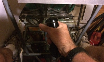
Work commenced on the biplane Sunday morning. Continued work on the pilot's flight controls, aka the stick-boot, etc.
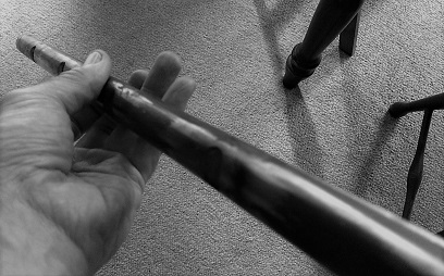
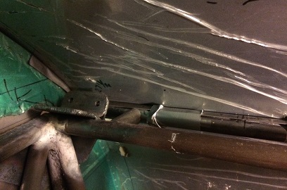
Welded the angled tube to the main stick-boot assembly after checking with it hooked up in the cockpit to make sure that it was as straight as I could get it. Followed that up with cutting off the 1 1/8inch tube from the first stick (that allowed me to attach the WWII grip to the 1inch stick shaft)... then positioned that and welded it on. Let that cool and tried it on for size.
Nice...
June 26 - 29, 2017
Openings are made for fittings...
NOT webbing !
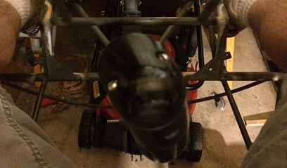
NOT sure what is going on with the front stick. When the back stick is vertical the front stick is listing to the one side about 1.5degrees. May not sound like much but it is.
Spent a number of days on trying to correct it while the torque tube is attached to the fuselage. First had to cut the angled tube off the front boot. And then... played with it for a few hours trying to make it work.
Thinking about it at work on Thursday I came to the conclusion that I need to work on this while the torque tube is OUT of the airplane. Need to make a jig where I can level horizontal and vertical THEN place the stick boots in the system and go from there. Who knows... I may have welded on the back angled tube (attached to the stick boot) at 1.5degrees? We'll see...
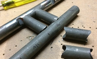
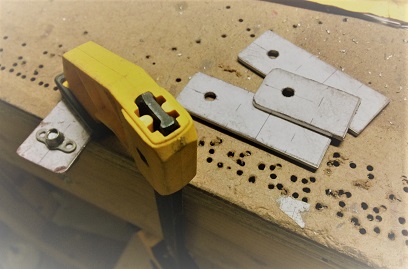
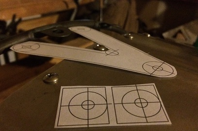
Anyways... instead of working on that on Thursday, I got workin' on the new seat-belt web guides. This will be the third go-round on these. In speaking with Scott at Hooker Harness (great guy, took time to speak to me about this small little detail)... he said that most of their fittings (on the end of the webbing for attaching to the fuselage) are 2.63inches wide. That ain't gonna fit through that 2inch opening I have on there now no matter how hard I try pushing it through.
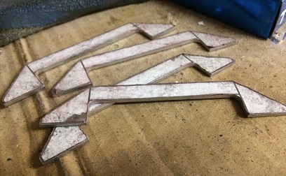
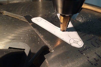
Drew the new guides on the CAD the other night and had them printed out. Spent close to two hours cutting out the rough blanks for all four (that does include time for changing out the saw blade).
Recently it seems like I'm doing more re-do's than new-do's.
June 30, 2017
New guides...
made for the fittings !
More work on the NEWEST webbing guides. I HOPE I have them the right size this time.
Worked on filing and sanding the four guides. Finished up with that in about an hour... took them out to the garage workshop and burned off the patterns. Still need to do a little more work on them (smoothing out the edges) before welding them on.
Spent the rest of my time (two hours) on grinding off, filing down, and sanding smooth, the existing four guides that were ALREADY welded onto the fuselage. Sweated my ass off...
July 1 - 2, 2017
New guides...
made for the fittings !
Working this ass-backwards, me thinks.
When I went and re-did the top of the pilot's stick-boot I should have taken the entire torque tube assembly off the fuselage and squared it up. Instead... I re-do the back boot with it in the fuselage then wonder... WTF happened with the front stick booth.
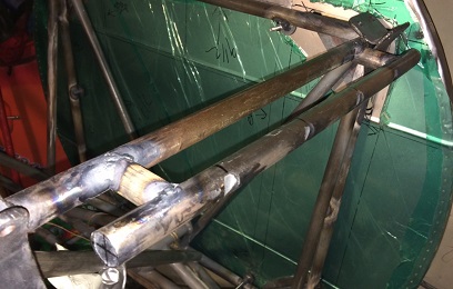
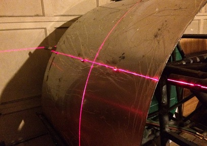
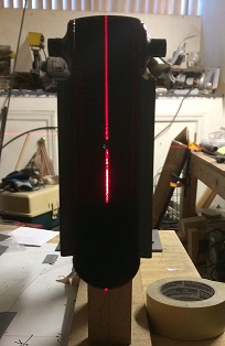
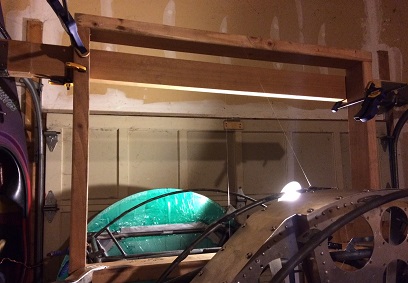
Cut the angled section off the front stick-boot and try to re-work that to vertical with no progress (as can be seen in a few days posts earlier). Took the entire torque tube assembly out of the plane and set it on the cradle-jig that I made it in (this time right-side up). Starting point... get the jig leveled both forward-back and side-to-side, then get the torque tube assembly anchored vertically (with the use of my handy dandy laser level)
Bolted the pilot's stick-boot/stick to the torque tube and it was near vertical ? A half a degree because of a little play, but... vertical. Went to the front side with the laser level and got it centered. Bolted the half-stick-boot on the assembly and got what seemed vertical. Then tried it with the stick to see if it went vertical the length of the tube. A tweak here and there and it seemed to be okay. Took it out to the garage and tacked it on in two places on the one side of the boot. Back down to try it out on the aseembly and it was off vertical. Luckily it was off vertical on the side that wasn't tacked. Carefully opened up that side of the stcik-boot by bending it open (using the two tacks as a hinge) and started sanding it down. Got it to the point where it looked like it closed enough to bring everything to where they needed to be. Out again to throw another tack on the other side. Back to try it again... and near perfect.
Took the entire torque tube assembly back out to the garage to try it out in the fuselage... hooked up the push-rods to the horizontal stabs and tried it out... worked like a charm.
Made the decision to have the front stick removal now... original one was welded in. This gives me the option of changing out the grip. I'll put on a standard grip right now... and when I find another WWII grip I'll switch it out.
July 3, 2017
Hand drawings...
it's for the birds.
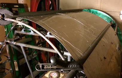
I need to figure out something for bending these side rails... the ones that I will be attaching the sheet metal too. It's been way too long waiting...
Since I ain't gonna be doing any of that stuff, I have to decide on what to do next. Looking at the fuselage there are a lot of little things that can be done. Which one to do ?
Probably spent more time deciding than doing. Saw that I needed to decide on how I wanted to attach the rear instrument panel. Figured... four attachments at the bottom and one or two at the top.
Positioned the instrument panel in place and took a few measurements... then had to hand draw the brackets. What a pain in the arse. I don't have a printer (of which I think I will be buying one now) that I could print out the CAD drawings. So... I didn't do any CAD drawings which are actually quick to do. Hand drawing is for the birds...
Well, I drew them up (a number of itirations) and glued the patterns on for cutting out. Drilled the holes for the anchor nut plates first then cut, grind, file, sand to size. They're ready for me to match drill the rivet holes for the anchor nut plates right now.
July 5, 2017
To the un-trained eye...
it's still there...
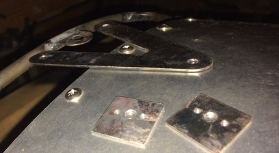
Working on this little stuff... the brackets that allow me to connect the instrument panels to the fuselage. Not very fast going, and when I'm done, it really doesn't appear that I've accomplished anything to the un-trained eye.
Anyways...
match-drilled the rivet holes for the anchor nut plates in each of the four instrument panel mounting brackets, for the pilot's panel. Figured out how to align... then tacked all four into position. Needed to break the one tack and re-align and tack again.
Enough time for one day (2.6hrs)... the re-tacked bracket needs to cool before testing again.
Think I figured out how to attach the panel at the top. Thinking a triangular-shaped bracket; two attach points to a bracket on the former just behind the panel, and one (maybe two) attach points on the top of the panel itself. This bracket needs to be removeable so that I can put in and take out the panel.
Short bracket for the front attachment.
Long bracket for the rear attachment.
July 6 - 7, 2017
A lot of custom made brackets...
to put it all together...
Working on this little stuff... again. But then... it's all little stuff until you put it all together to form a biplane.
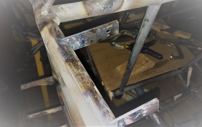
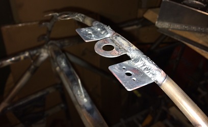
More work on the back instrument panel. Welded on all four lower, attaching brackets. Then... got to work on figuring out how to stabilizer the top of the panel. Came up with pattern that would have a single attach point on the top of the panel and two attach points on the former just in front of the panel.
Instead of hand-drawing it (which we discovered was for the birds) I drew it up on the Delta CAD program I have. Having done that... I needed to go out an buy a printer.
Next day (Friday), I went out and picked up a printer from Staples; a "plug and play" model with blue tooth. Brought it home. Plugged it in. Had my computer do a search for it... and it auto-installed. Printed out the CAD... and I was ready to go. Took the CAD out to the project and did a test fit to see if it would work... and it did.
Grabbed a sheet of .050 4130 and spray mounted the patterns to it. After one point seven hours I had it and both mounting tabs cut out, filed and sanded; ready to be mounted to the fuselage. Did a quick look-see to see how it looked on the frame. May be a little close, the bolt that I will be using and the aluminum sheet metal skin that will wrap over top of it. I'll need to a sheet of aluminum in place to see how much room I actually will have before filing a little bit more off the bottom of the instrument panel.
Finished bracket and tab mounts.
This post got me to thinking about the guys having their brackets waterjet cut. Little do they know that they're going to need to custom fashion brackets for attaching all kinds of things; instrument panels, tabs for mounting flooring and sheet metal skins, antennas, etc etc etc...
July 8, 2017
Two tabs...
That's all, folks.
Reall quick... weld on the two mounting tabs and off to another project... or so I thought.
It took me close to one and a half hours to align, tack and weld those two mounting tabs onto the former. WOW ! Not much more I can say about that other than... I didn't accomplish anything else today.
July 9 - 10, 2017
It's just time, folks...
just, time.
okay... the back instrument panel is basically locked into position (just need to drill the holes in the instrument panel box and rivet the one anchor nut plate to the top of the box)... so, it's off to do the front panel. Not quite as easy.
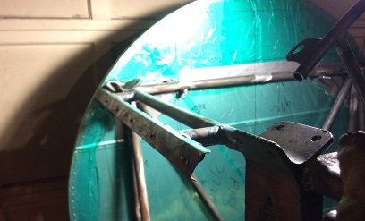
With all this sway wire stuff going on... the front panel, as it is made right now, needs to have some modification done to it. With that said, I need to jig the rear spar in position to see where these wires are going to fall. And of course, this all take time, quite a bit of time actually. So... it's all in place now with the pseudo wires (fishing line) in place to give me a sense of where the wires will fall. I cut out a paper template of the front panel. Cut a few holes in it... and start evauluating things.
Came to the conclusion that... doing it this way is kind of just wasting my time. It may be good for an approximation, but until I have the actual upper wing center section in place with the actual wires... it's all just adding time to the build.
August 12 - 19, 2017
It's time to bend the side-rails...
again.
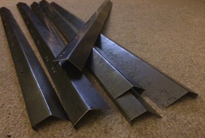
I reached out to Tom McDowell again... the president of our local EAA Chapter... 216. He was busy and had forgotten to get back to me (it happens). He apologized and said he'd contact a few guys he knew that had a metal brake. Got back to me pretty quick and we lined up Friday for the day to go over to a friend's place to do the bending.
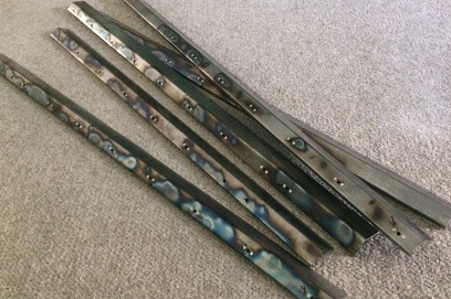
About an hour later and I had all the side-rails, plus one, bent to the correct angles... and straight as arrows ! Thank you Tom !
Spent the next two days dimpling the rivet holes and cutting down the rivets for riveting in the anchor nut plates. Tomorrow I'll start the riveting...
August 20 - 25, 2017
It's time to...
do more of the same, again.
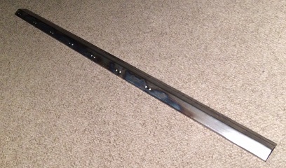
Spent time working on these new side-rails. Needed to clean the patterns off then begin the process of riveting on the anchor nut plates. De ja' vu.
At this point I've riveted them all on... now I need to go back and drill out a few of them.
First one.
All of them.
August 26, 2017
It's time to...
do more of the same, again. Yeah, again.
More work on the side-rails. Bad, bad rivets.
Drilled out. Riveted. Re-drilled out a few. Riveted. Done
September 1 - 4, 2017
It's time to...
make more work for myself. Yet, again.
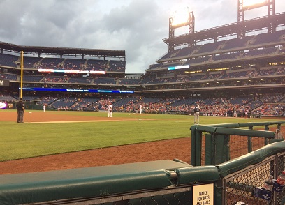
Planned on working on the project on Monday... to start on the side-rails again. Last minute opportunity to go to the Phillies game (GREAT seats!) and went...
They won, 6 - 1.
Over the past few days I've been thinking hard about that upper wing center section. A few possible things I'll be doing. But... decided to get back on the sheet metal part of this project.
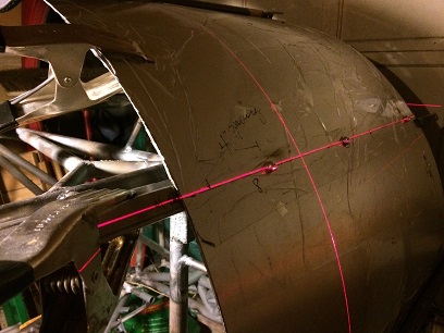
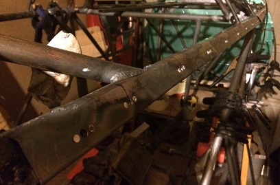
Friday, I began aligning the starboard-side side-rail. Used my laser level this time. In doing so, I discovered that, level, the front touches the pseudo longeron and the rear (only about 24inches back) is off the longeron 3/16 of an inch. Not good for welding. Sat and thought hard about that for 1/2 hour. Came to the conclusion that the best way to fix it was to cut the pseudo longeron off and re-align it and then weld it back on.
Spent three hours doing just that; cutting it off and filing down the excess weld. I'm now ready to cut the stand-off pieces, weld, and get on with this side of the side-rail alignment. The other side... we'll see when I get to it.
Ready for re-attaching.
September
5 - 15, 2017
Time to tack...
and
get those sails full of wind again.
Continued working on the re-do's of the pseudo longerons.
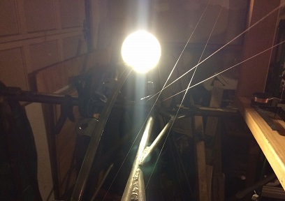
Decided to use my laser level for making sure all three side-rails
on each side are as straight as I can get them; in-line with
each other. BEAUTIFUL !
Working through each one... like I did the first time. Once
I get them aligned and tacked, I then clamp on the piece of
retangular tube I purchased to make sure that they are as
straight as I can get them (they bow a little when I cut down
the one leg for fitting).
It's been slow going... mental more than anything else. When
you've put all that time and effort into completing a project
and then only to come back and basically cut it back to starting
over... kind of takes the wind out of your sails.
September 17 - 20, 2017
Repeat...
repeat repeat repeat
Continued working on the re-do's of the side-rails.
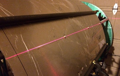
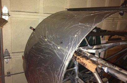
The laser level works great keeping things all on the same line... Plugging away at getting these on there as straight as possible, and to keep the bows out of the side-rails.
Keeping the bows out of the side-rails is being problematic. I ended up cutting the welds off the second, starboard side-rail because of the bow in it (though, just a slight bow). Now I'm just tacking both ends and one center point of the side-rails once I have them aligned. I get it as un-bowed as possible before tacking. Then... once I pull the sheet metal off of it (that I used for aligning) I check for the line on the laser level and the bow. If bowed... I cut the center tack, clamp on a rectangular tube, re-tack, re-check for un-bowedness (wurd?) and if good... do complete spot welds on the side-rail. This seems to be a good procedure for getting things straight AND un-bowed.
Jigging third starboard side-rail.
Third side-rail locked in position.
Starting on the port side...
September 22 - October 3, 2017
More...
repeat repeat repeat
Continued working on the re-do's of the side-rails.
Decided to re-do the pseudo longeron on the port side also. Worked my way through that... the same as I did on the starboard side.
Aligned, measured and cut the new side-rail for the first station on the port side... for the second time (alluding to the first time that I did this). Did everything as I did on the other side.
When it came to putting it on the fuselage... I mounted it to the sheet metal, aligned to make sure that the bolt heads fell on the laser level line. Tacked it on both ends. Removed the skin. Clamped on the rectangular bar. Used the smaller clamps to clamp the side-rails to the bar... same as the other side. BUT, this time after removing the clamps, after having tacked it every two inches... I looked at it and it was WARPED ??? What ?
Cut the tacks off (what a pain in the arse!). Clamped the bar on... watched as I clamped the smaller clamps and saw that instead of pulling it to the bar it was actually pushing it away (GO Figure)... THUS putting a bow in the side-rail. Decided to sans the clamps this time and it came out damn near straight.


 When I went and re-did the top of the pilot's stick-boot I should have taken the entire torque tube assembly off the fuselage and squared it up. Instead... I re-do the back boot with it in the fuselage then wonder... WTF happened with the front stick booth.
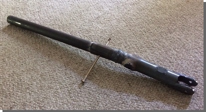

 First one.