Mantua, New Jersey
Original Site:
September 2004
E-mail: usav8or@yahoo.com
The Empennage... looking to build the tail section..
10/19/06:
Taking a look at the plans to see what tubing needs to be
ordered to bend and weld up the tail section.
Asked the question to the biplaneforum.com group...
What did you use to bend the tube ? And, did it work for
you or would you have done it a different way if you had to
do it again?
Also, what should I look out for when making that BIG round
bend ?
Randy's Answer:
" I cut a 8" dia. circle on my band saw out of 3/4"
MDF, sanded the bumps off and screwed it to my wing assembly
table. Screwed a block to the table about 8" from the MDF
to "capture" the tube while bending it around the MDF.
I laid out the outline of the Vert. stab. on the table and
drove some #8 nails on the outline leaving them stick up 1"
or so. These are just to have something to push the bent tube
against. Then just start bending a little at a time. You need
a piece of tube about 24" longer than called for just to have
some leverage to bend with.
You don't need to pack the tube with sand. It bends quite
easily just go slow and compare to your pattern often. DO
NOT APPLY HEAT. I guarantee that to bend and kink. I do it
flat on a table rather than a vice as it helps me keep the
tube flat, all on the same plane. (So to speak) The rudder
and vert. stab. are quite easy to bend to shape. The hor.
stab. leading edge is a total 'nother story. I welded one end
shut, packed the tube with sand. Tapped it on the floor often
to settle the sand and drove a hardwood plug in the other
end. Now heat can be applied - sparingly - to help in bending.
"
I'll let you know how it turns out. I'll upload pictures
of the jig and the finished product too.
January 10, 2007: Update
On
Monday, January 8th, I bought a Smith Airline Tourch Welding
rig from Wag-Aero's online store. From what I discussed with
the guys on the biplane forum, a smaller system such as this
is all you need for 99.9% of the welding that you will do
on a homebuilt. That other .1% would be for welding up aluminum,
and that I can leave to the specialist. You can read about
my buying decision on my welding
page.
I should have the rig by the end of the week. I have the tubing for the empennage and
practice parts at the house already. I also purchased a DVD and EAA book on welding. I'll be burning
holes in 4130 next week sometime.
March 22, 2007:
I'll be making the bending apparatus for the tail feathers this weekend. I'll make up one of those photo essays to show you what I did
and I'll let you know if it works or not. Click here to see what I've done.
April 16, 2007: FINALLY... I've gotten a chance to layout the vertical tail for the empennage. Took about an hour to do... not hard at all. One caveat,
the measurement top to bottom is OD, Outside Dimensions, all the other dimensions for the vertical tail are OC, On Center. Just a little
something that you may want to keep in mind. An obvious that may not be so obvious.
I laid the pattern for the tail on a piece of 1/2" plywood. At each point that the plans give you for plotting the curve of the tail I nailed a finish nail
into the plywood. After putting a nail into each plot point I took a piece of welding rod and bent it to form the curve of the tail.
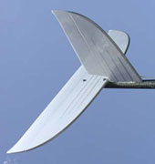
Viewing the Skybolt in the past I always thought it had a perfectly 1/2 round rudder. That ain't the case... it's a little flat on the bottom gradually taking on more of a circle likeness as you move up
the tail.
This is a huge milestone for me in the project. I've worked on nothing but aileron parts and ailerons for so long that anything other than ailerons is
a welcomed change.
When
you go to shape the curve to your rudder make sure that it's
on a flat table. Let me say that again... When you go to shape
the curve to your rudder make sure that it's on a flat table.
Did I just say a flat table ? Make that a LARGE flat table.
Or, at least set your bending jig up so that there is a sizable
amount of tubing left to bend on one side of the LARGE flat
table and a sizable amount of tubing already bent on the other
side of the LARGE flat table.
I just spent a little over 2 hours learning what NOT to do.
Not a bad thing. The only thing I lost was a night's worth
of time and about 5 ft of 3/8" .035 4130 tubing. I gained
a little practice in bending technique.
As always,,, I did my homework before I began bending. I just didn't
think it through, I guess. Makes sense to have a flat surface
on both sides of the bend. What was I thinking ? I had the
bending jig right up against the side of the table. Once the
tube was bent and moved through it hung over the side of the
table with nothing giving me a reference to wether it was
still straight or not. I figured that the 15" or so of bend
on the table was reference enough.
WRONG
I can't believe that I made this mistake. I knew there would
be a day that I would learn from a mistake, but not this.
It was such a simple procedure. Or so I thought. Maybe that
was my first mistake... thinking that anything in building
a plane is simple. It all requires thinking things through.
Even the supposedly simplest of processes.
Above you can see the slight bend in the tubing. You can actually see where it was hanging over the end of the table and starting to drift
down and to the right. It looked pretty damn good from the side, the curved to it. But as you can see... it was a little less than straight front to back.
I was so focused on getting the correct radius to the tubing that I failed to notice the slight side-ways bend I was making. Guess I can cut this up and use
it for a wind chime this summer.
Tomorrow... making another pass at bending the rudder.
After I've bent the rudder correctly I'll let you know how I did it the right way.
It's Sunday and I have a few hours to tackle making this rudder again.
Modified my workbench by extending it an additional 48". This alleviated the problem I had with the tube twisting and heading south on me.
One hunderd and eighty minutes later I have a nice looking trailing edge for my rudder.
I modified the bend slightly. The measurements that the
plans gave me seemed to be a little out of "rounds."
Why, you may ask, did it take me soooooo long to bend the tubing a half a circle. First off.. this was my second time around with it so I might have been
a little over cautious. Better to be over cautious than to waste a few hours with a piece that would, again, be unuseable. I checked, re-checked then re-checked every few inches that I bent. The hardest part of the process was making sure that the tubing stayed straight on the
workbench, and that wasn't hard.. just a matter of taking your time.
I modified the bending block for the task also. I added a sliding block to the brace block. This allowed me to keep more of the tubing over the flat surface of the table
rather than allowing the unbent portion to hang over the back edge of the table. The sliding block is the 2 x 4 that you see in the photo to the right. Depending on where I was at with the tubing, I would
adjust the block to keep most of the tubing on the table, then screw the block down to my workbend. Simple. I like....
Oh... and another thing. Lay your pattern on the floor, or some flat surface. If you check the bend of the rudder on the pattern while it's standing on it's end, gravity will tend to pull the tube down
and give you a false reading on your bend. Just a heads up.
The photo above is a dead on shot from the backside of the rudder. Nice and straight this time, isn't it. The shot you see here is taken from the side just a bit. I had to show off that beautiful looking curve, the
trademark of a Skybolt.
Next... I'll be making the stabilizer leading edges. A little bit more challenging, I think. Two of the exact same shape ??? YIKES !
On to building the stabilizers. To read more... click here.


 10/19/06:
Taking a look at the plans to see what tubing needs to be
ordered to bend and weld up the tail section.
10/19/06:
Taking a look at the plans to see what tubing needs to be
ordered to bend and weld up the tail section.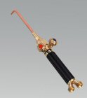 On
Monday, January 8th, I bought a Smith Airline Tourch Welding
rig from Wag-Aero's online store. From what I discussed with
the guys on the biplane forum, a smaller system such as this
is all you need for 99.9% of the welding that you will do
on a homebuilt. That other .1% would be for welding up aluminum,
and that I can leave to the specialist. You can read about
my buying decision on my
On
Monday, January 8th, I bought a Smith Airline Tourch Welding
rig from Wag-Aero's online store. From what I discussed with
the guys on the biplane forum, a smaller system such as this
is all you need for 99.9% of the welding that you will do
on a homebuilt. That other .1% would be for welding up aluminum,
and that I can leave to the specialist. You can read about
my buying decision on my 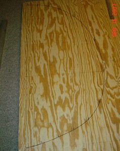 FINALLY... I've gotten a chance to layout the vertical tail for the empennage. Took about an hour to do... not hard at all. One caveat,
the measurement top to bottom is OD, Outside Dimensions, all the other dimensions for the vertical tail are OC, On Center. Just a little
something that you may want to keep in mind. An obvious that may not be so obvious.
FINALLY... I've gotten a chance to layout the vertical tail for the empennage. Took about an hour to do... not hard at all. One caveat,
the measurement top to bottom is OD, Outside Dimensions, all the other dimensions for the vertical tail are OC, On Center. Just a little
something that you may want to keep in mind. An obvious that may not be so obvious. 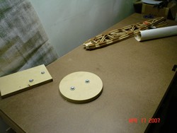 When
you go to shape the curve to your rudder make sure that it's
on a flat table. Let me say that again... When you go to shape
the curve to your rudder make sure that it's on a flat table.
Did I just say a flat table ? Make that a LARGE flat table.
Or, at least set your bending jig up so that there is a sizable
amount of tubing left to bend on one side of the LARGE flat
table and a sizable amount of tubing already bent on the other
side of the LARGE flat table.
When
you go to shape the curve to your rudder make sure that it's
on a flat table. Let me say that again... When you go to shape
the curve to your rudder make sure that it's on a flat table.
Did I just say a flat table ? Make that a LARGE flat table.
Or, at least set your bending jig up so that there is a sizable
amount of tubing left to bend on one side of the LARGE flat
table and a sizable amount of tubing already bent on the other
side of the LARGE flat table.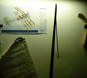 I can't believe that I made this mistake. I knew there would
be a day that I would learn from a mistake, but not this.
It was such a simple procedure. Or so I thought. Maybe that
was my first mistake... thinking that anything in building
a plane is simple. It all requires thinking things through.
Even the supposedly simplest of processes.
I can't believe that I made this mistake. I knew there would
be a day that I would learn from a mistake, but not this.
It was such a simple procedure. Or so I thought. Maybe that
was my first mistake... thinking that anything in building
a plane is simple. It all requires thinking things through.
Even the supposedly simplest of processes.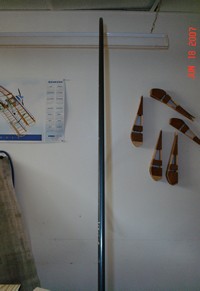 I modified the bend slightly. The measurements that the
plans gave me seemed to be a little out of "rounds."
I modified the bend slightly. The measurements that the
plans gave me seemed to be a little out of "rounds."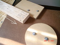 I modified the bending block for the task also. I added a sliding block to the brace block. This allowed me to keep more of the tubing over the flat surface of the table
rather than allowing the unbent portion to hang over the back edge of the table. The sliding block is the 2 x 4 that you see in the photo to the right. Depending on where I was at with the tubing, I would
adjust the block to keep most of the tubing on the table, then screw the block down to my workbend. Simple. I like....
I modified the bending block for the task also. I added a sliding block to the brace block. This allowed me to keep more of the tubing over the flat surface of the table
rather than allowing the unbent portion to hang over the back edge of the table. The sliding block is the 2 x 4 that you see in the photo to the right. Depending on where I was at with the tubing, I would
adjust the block to keep most of the tubing on the table, then screw the block down to my workbend. Simple. I like....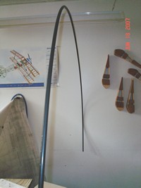 The photo above is a dead on shot from the backside of the rudder. Nice and straight this time, isn't it. The shot you see here is taken from the side just a bit. I had to show off that beautiful looking curve, the
trademark of a Skybolt.
The photo above is a dead on shot from the backside of the rudder. Nice and straight this time, isn't it. The shot you see here is taken from the side just a bit. I had to show off that beautiful looking curve, the
trademark of a Skybolt.